
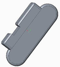
On-Off Switchplate
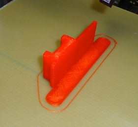
We decided to design a new plate to surround the main power on-off switch for the robot using the CAD and 3D printer. We wanted something useful and simple for our first attempt at CAD and printing the switch cover seemed a good choice. We watched a team’s robot get turned off in competition because their on-off switch was hit by a part from another robot. We realized that the plate that the switches come with is completely flat but that many on-off switches are recessed or protected to prevent accidental activation like we saw at competition. Rob & Jordan disassembled one of the current switches and measured it for all dimensions (hole placement, central opening, etc.) and then Ethan and JP used the CAD software to copy that design. Then we added walls that were perpendicular to the plate on each side of the opening for the actual switch. The project worked well and we installed the new switch plate.
We realized that there are very few parts that every robot in FTC MUST have in its design. The On-Off switch is required, and it must be easy accessible by referees during the competition. This realization helped us see that we could help other teams by printing extra CAD switchplates and giving them out at events. Over the course of the 2014-15 season we have given out nearly 200 switchplates to other FTC teams. Because GENIUS Girls and Circuit Runners were so much help to us at various points in the season we printed their versions in their team colors for them. Most of our switchplates are in what the company calls red but looks rather orange to us.

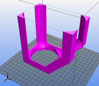
Ball Scoop
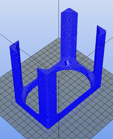
We had a ball scoop design at our first qualifer that was heavy and bulky needing two motors to lift. As we worked with the 3D printer we realized that the plastic was tough enough to work for this use and much lighter. The scoop that we designed needed to be at least 9.5 inches long, but our printers bed was <8 inches. After going back and forth on whether we needed to change the design we realized that we could split the ball scoop into two pieces, print them seperately, and then fasten them together mechanically using the arms of the lift mechanism to tie the two pieces together.
We Worked to print the back of the ball scoop first. The larger items are not sticking to the printer surface through the print, so we researched online how to improve adhesion by the printed plastic through the entire print job. We will be trying Unscented Aqua Net® as recommended on several sitesin an attempt to improve this issue. We also realized that the room is cooler than the specs call for in printing (it’s winter) so we have placed a portable heater next to the 3D printer to keep the print area at a constant 70°F during printing. We are using a print scale of 0.22 to get the right physical size we want.

Lift Arm Stop
Our robot uses two sets of lift slides (cabinet drawer slides) to raise our ball scoop to the appropriate height to place balls into the various tubes used in Cascade Effect. The lift slides had two areas that they needed limiting – they went down too far and put stain on the cables and when the lift arm swung it could go too far and hit the motor and sensor controllers thereby increasing the chances that they might fail. We designed two CAD parts to address these issues. The first is the Lift Arm Stop which limits how far back the lift arm can swing as it gets into position to place balls into tubes.
CAD & 3D Printed Parts
We started learning about CAD and 3D printing during the Christmas break in 2014. We won a 3DSystems Ekocycle printer but it wasn't delivered until late January so Mr. Westin, one of our coaches, loaned the team his K8200 printer to learn on. We also were fortunate that PTC allows FIRST teams to use a student version of Creo for free. We would like to thank Mr. Westin for loaning his printer and for his time in teaching us how to use the printer and CAD software. We would also like to thank PTC for providing Creo to FIRST teams and 3DSystems and Coca-Cola for sponsoring the 3D Cube printer program for FIRST.
The parts listed below are ones that we developed for use on our 2014-15 robot used in Cascade Effect. Once the 2015-16 Game is released we plan on updating this section with our new 3D parts for this season's robot. If you want more information on any part please contact us and we will provide all technical details so that your team can reproduce the CAD part for your own use.


Slide Stop
As we said before with the Lift Arm Stop part; Our robot uses two sets of lift slides (cabinet drawer slides) to raise our ball scoop to the appropriate height to place balls into the various tubes used in Cascade Effect. The lift slides had two areas that they needed limiting – they went down too far and put stain on the cables and when the lift arm swung it could go too far and hit the motor and sensor controllers thereby increasing the chances that they might fail. We designed two CAD parts to address these issues. The first is the Lift Arm Stop which limits how far back the lift arm can swing as it gets into position to place balls into tubes. The second were Slide Stops that limited the downward movement of the nested cabinet slides so that they did not over extend and damage the field.

L-Braces
Initally this part was desiged to hold the front ramp on our robot used to collect balls into our scoop. We wanted a part that was light and rigid that was a specifc length and had little lateral flex. Ethan and JP designed this part with build in braces so that the part would not flex as much side-to-side. The inital design proved to be too thin (it broke quickly) so thickness of the part was adjusted by 200% and the resulting parts have worked without fail since throughout many matches.
We later realized that we could use this part to help prevent balls from getting trapped in the interior of our ball scoop area when the ball scoop was extended on the lift arm which left a large open area in the middle of the robot. Several were then added to the sides to help prevent balls from entering that area.

Ball Stop
Some parts don't make the final cut - the Ball Stop is one of them. We used it to stop balls from prematurely falling out of the front of the ball scoop when we had our initial design for the scoop. We used plastic instead of metal for two reasons - weight and we did not want to damage the balls used in the game. However, when we redesigned the scoop after a change in the interpretation of the rules regarding incidental touching of the field tubes we realized that we needed to have a different shape and style part completely and so redesigned the ball stop. This part was used during a qualifer match but was replaced prior to competing at State.


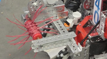
Spinner Shaft
We used various materials to try to collect balls and move them into our ball scoop in the beginning of the season. We tried to directly scoop them but, as we learned at our first qualifier where we did very poorly, that did not work well at all. We watched several teams use zip ties on a spinner to whip balls into the interior of the robot in order to move them up into a tube.
Our spinner had many challenges. It was orignally built from a cut piece of PVC pipe, which gave very little to fasten to. It also was not well centered on the axle we had it mounted on. The 1.25” diameter was good, but the rest could be improved. A new 3D printed version appears to be a much better choice:
-
Provide holes to match the brass to spin on
-
Provide screw holes for attaching the drive gear
-
Ridges to help the zip ties stay in place
We designed it with a hole all the way through, and with screw holes on both ends. Rob has been waiting for a chance to change the zip ties to be in line with team colors, so this was his chance. Later we added surgical tubing to the tips of the zip ties at the suggestion of one of our former team members who was visiting and that added to the effectiveness of this design in moving balls into the scoop.

Ball Ramp Neck
We had a gap between the Ball Ramp and the Ball Scoop that balls were getting hung up on the transition between the two due to a gap. We designed a part that filled the gap, guided the Ball Scoop into the niche in the base of the robot, and had cut outs for the servo and other parts attached to the Ball Scoop and the base of the robot itself. The initial model had some extra material that caught and didn't install properly, so we used power tools to trim it to fit and then used that version as our model to print an updated version 1.1 that fit more precisely. As with several other parts, the need for this part disappeared when we redesigned other aspects of the robot and eliminated the gap that this part was designed to fill.

Wheel Guards
We have had small ball issues with the large 5” All-Terrain wheels so we decided that
we need guards to deflect the small balls away from those wheels. The design is very simple but they appear to do their job. They were mounted in front of each of the 5" All-Terrain wheels to help prevent balls from getting under the wheels and lifting the entire robot , which allowed it to get stuck on field elements. We used the guards at the Wheeler Qualifer and at the State Championship but they were removed for the South Super-Regional Championship because of other design changes that made them unnecessary.

NXT Brain Mount
Last season we had a very functional NXT brain mount made from Lego® parts but the small pins that inserted into the NXT itself to secure it to the frame often pulled out and were lost as a result. We decided to design a new CAD mount will be more precise and would avoid that problem. We ran into spacing and sizing problems and this part was one of the hardest to get just right for installation. We stuck with it and are now using our NXT Brain Mount on our robot in competition. No failures, easier to access the NXT, and we're able to mount it precisely where we want it on the robot.

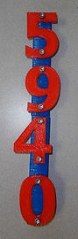
Side Number Mounts
The game rules require that you have numbers that are 2" high each mounted to your robot on a contrasting background. They also have to be visible from 180 degrees. In looking at our robot we realized that mounting to our lift slides gave us enough room and met the rule requirements. JP designed these mounts with a hollow center and a slot so that we could run our vertical wiring along the outer sides of the lift mechanism but have them be protected from damage by other robots. We mounted our team number in individual digits vertically directly to these parts.
Combined the Team Numbers and the Side Number Mounts and placed on each side of the Robot complies with rule <RG09>.

Scoop Drop
There were changes in the interpretation of rules for Cascade Effect that occurred between our first qualifier and our second qualifier at Wheeler. The discussion happened in the Official Forums and revolved around robots touching the tubes during placement of balls. We received several penalities during the Wheeler Qualifier because our design involved touching the lips of the tubes consistently. The touching the ball tubes issue really complicated things for us at the Wheeler Qualifier. We know that we will have to address this issue prior to competing at State to have any chance at all of being competitive. One idea was to use a piece of CAD designed plastic that folds up and used gravity to guide the balls out of the scoop and drop them straight down into the tube opening. Ethan and Mr. Westin worked on this design and we printed a Proof-of-concept part to do field trials with on the robot.

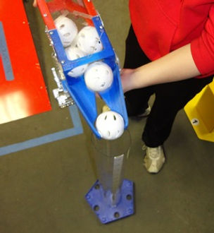
Ball Scoop Front Redesign
Our Ball Scoop has gone through many revisions over the season. After the rule interpretation change we needed to change the front of the scoop and make it allow more easy movement of the balls out of the scoop when it was raised into place. We tried several designs but had to stay within the dimensions we had for the interior space the scoop had to fit into on the robot when in the stored position to gather balls from the field. We couldn't make the part taller in that position so we widened it and made the opening an oval shape instead of a circle. This worked well in gathering the balls and allowed them freedom to roll out when gravity took over without catching on the opening itself but this also meant we needed a way to control when the balls exited the scoop.

Ball Blocker
Because the scoop opening was larger allowing balls to freely roll out when gravity took over we needed a way to stop them until the scoop drop was in the right position to score points by dropping balls into the tubes. A servo activated ball blocker was needed but the old design was too small and did not cover enough of the width of the opening to reliably stop the balls from rolling out. JP & Ethan designed a new part that was wider and had a purpose built attachment point for the connection to the servo.


Sensor Mount
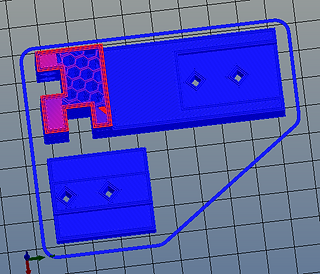
The IR and Ultrasonic sensors need to be placed high and together to make wiring and control easier. In combination they give us a precise way to determine the location and orientation of the center unit in the game. We tried some standard Lego parts but they just weren’t strong enough to be stable when the robot ran into the wall or another robot. We realized that this was the same issue that led us to designing and 3D printing the NXT Mount for our robot so we designed a mount that would fit on the top of the Tube Capture spike slide.
The IR and Ultrasonic fit into the notches marked in pink above with one at the top and the other at the side of the mount. Our first attempt on replacing the Lego parts with a 3D part resulted in a tall unitl that held the sensors but was too tall to meet the height limit of 18 inches overall. We shortened the sensor mount which met the height requirement but when installing it we noted that a slight shortening and minor repositioning of the bolt holes would align perfectly with the slide head. We designed the holes in the mount so that the standard bolts are self-tapping thereby increasing strength and reducing parts. The final product fits in the space perfectly, is rock solid when installed, and orients the two sensors properly to maximize their utility and accuracy for our autonomous program.

The ball scoop can’t touch the ball tubes according to the new interpretation of the rules regarding touching the tubes. Our old design had balls catching at the opening and shaking the scoop back and forth was needed to dislodge them. When we did that in competition we often touched the tubes and either got warnings or penalties. We need to redesign the Ball Scoop front in order to eliminate touching the tubes. The Scoop Drop that we redesigned based on the DarBots design guides the balls consistently to the center and drops them straight down into the tubes. This change means that we now need a larger opening on the scoop front to eliminate the catching of the balls we had with the old design. Because the Scoop Drop guides the balls consistently to the center with no problems a large oval opening for the scoop front would be the best way to get the balls into and out of the scoop itself and allow the Scoop Drop to guide them into the correct position for dropping into the tubes.